 by Mike Brooks |
Last Updated: June 25, 2022
by Mike Brooks |
Last Updated: June 25, 2022 Do you know how to accurately calibrate your 3D printer to ensure the best performance and get the best returns on your investment?
As an Amazon Associate, I earn from qualifying purchases. If you make a purchase after clicking on a link I may earn a small commission at no extra cost to you.
Does your 3D printer calibration affect the print quality of the finished print?
Quick Navigation
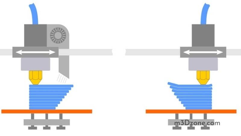
If your printer’s nozzle is too close to the print bed, the first layer of your print can become squished and destroyed. Thus, you may have to cancel the print.
On the other hand, if the nozzle is too far from the print bed, the print may not have adhesion and will fail.
You can work on your first layer by fine-tuning the Z offset. The Z offset tells your 3D printer how far you should move the Z-axis from the Z end stops or the printer bed.
However, learning how to fine-tune all the motors can be a challenge for beginners in 3D printing. But once you calibrate one motor, you’ll have an easier time calibrating the others.
The goal of accurate calibration is to ensure the first layer of your print sticks to the print bed.
So, how do you calibrate a 3D printer?
What Do You Need for the 3D Printer Calibration?
- A 3D printer with a software
- Filament
- Tape
- Ruler ( 40cm)
- Digital calipers
- A pad of paper and a pencil (check at Amazon)
Before starting the calibration, ensure you have a level print bed and a square frame to help you get the expected results. Without the two, there are chances of the print head melting into the print bed, leading to unpleasant outcomes.
What Is a Calibration Cube?
A calibration cube refers to a geometric shape that helps you to fine-tune your 3D printer settings. You can also use it to tune the millimeter settings.
The cube informs the motors on how much they should turn to move by one millimeter.
Calibrating the Stepper Motors
3D printers come with stepper motors that rotate using small steps to move the extruder and the axes a particular distance. If the rotation is 100 steps, the stepper motor rotates 50 times to turn half a rotation.

Calibrating the motors in a 3D printer involves determining the relationship between distance and the steps. To achieve the best extruder calibration, you should ensure the printer is not extruding too much filament.
Thus, you have to send some G-code commands to your 3D printer.
You can use the following steps to calibrate your motors:
1. Prepare Your Calibration Values
Here, you compare the settings of your 3D printer with how it prints. You should do some calculations to correct any discrepancies.
- First, send your printer command M503 to retrieve its settings. Some of the output after entering the command includes Steps per unit: M92 X100.00 Y100.00 Z400.00 E140.00.
- The first three values from the command correspond with your stepper motors’ steps to move one millimeter in the X, Y, and Z directions. The last value on the output represents the steps your extruder motor takes per millimeter of filament extruded. You can mark the last number as A.
- After that, insert your filament and put a mark of about 50mm on top of the extruder. You can use calipers (check at Amazon) to get the actual value and then mark the value as B.
- Next, extrude about 10mm of filament and measure the value from the extruder’s top to the marked point. You can mark the value as C. As such, B-C is the actual measurement of the extruded filament.
Your extruder is calibrated correctly if B-C=10. Otherwise, you need to update the steps of the extruder per millimeter. Thus, you can come up with the following value D = 10*A / (B – C). The new value represents the steps per mm for the printer’s extruder.
2. Calibrate the Extruder
To start calibrating your extruder, you need to inform your 3D printer of the new value.
You can inform the printer of the new value by sending the command M92 E[D].
The command will inform the printer of the new value, but it will not save it. You should use the command M500 to save the new number on the printer.
As you calibrate the axis, you shouldn’t expect perfect outcomes. You’ll experience some variations as you confirm whether your calibration is correct. However, your printer is well calibrated if you are close to the desired value.
3. Calibrate the 3D Printer Axes
After calibrating your extruder, you should then calibrate the axes of the 3D printer. Calibrating the axes follows the same process as calibrating the extruder.
However, while calibrating the axes, you require to print something.
You should ensure you calibrate the extruder before calibrating the axes, as the extruder can affect the size of your printed object.
To calibrate the axes, you can start by printing a small cube. You can design one using CAD software of your choice.
When the small cube has finished printing, measure the dimensions. In the next step, repeat the computation for each axis as you did with the extrude, i.e., D = 10*A / (B – C). However, ensure you replace the variables with new values as follows:
- (B – C) with the new measurements
- the number 10 with your target value of the new measurement
- the value you got in step 1 after sending the command M503 with the M92 value for the particular axis
Finally, send the M92 commands to your 3D printer and replace the E with the letter of the particular axis you require to set.
It will be best to take multiple measurements and have their average as you did with the extruder.
You don’t have to start printing multiple objects to measure. Instead, you can measure different positions of the cube along the same axis.
4. Measuring the Value of the X-axis
When you want to measure the value of the X-axis, you should start by homing the X-axis and getting the Z-axis aside.
Take a tape, most preferably a less flexible tape, and put it on your printer bed. The tape should be on the point of the 3D printer that won’t move when moving the X-axis.
Next, tell the 3D printer to move its X-axis. If you use a 100x100x100mm printer bed, it will be best to start at 70mm. You can push the axis further, provided you don’t go beyond the printer’s capabilities.
It would be best to use another tape to mark the point you started before moving the axis. This is the point your printer thinks the 70mm is.
After that, you can use your calipers to measure the actual measurement for the X-axis. If the measurement is 70mm, then your x-axis is appropriately calibrated.
You may not get 70mm precisely on your first trial, but you should note the measurements you took.
5. Calibrating the Y-axis
Calibrating the Y-axis is similar to calibrating the X-axis. The only difference is in where you stick the tape to measure the movement of the Y-axis.
First, you should home your X, Y, and Z-axes. In the next step, move the X-axis until it is in line with the most outer part of the 3D printer.
Next, put a tape on the Y-axis over a point you mark on the X-axis. Move your Y-axis to 70mm and mark the point using tape. You should then measure the actual distance between two points.
You can use the two measurements and the current M92 value to solve your new m92 value.
6. Calibrating the Z-axis
You can use a ruler instead of digital calipers to measure the Z-axis.
First, you should home your x, y, and z axes. Next, you should place the ruler perpendicular to the print bed. After that, move your eye to level with a particular point of your 3D printer, such as the tallest part of the arm.
Ensure that your eye is level with the point you want to measure when taking the measurements. Next, instruct your printer to raise 100mm and then check how far the printer has moved.
Subtracting the second measurement from the first helps you discover whether you have overshot your printer.
Fine-tuning the Settings of Your Filament
Every roll of filament comes with its properties. Plastics from different manufacturers and colors of the same material are different.
To get the best print, you should fine-tune the settings of your filament. You can get high-quality prints by using settings that the filament manufacturer recommends.
You can use the following steps to fine-tune the settings:
a) Measure the Filament
The diameter of a filament spool can differ from the one reported by the manufacturer by a small percentage. Thus, it would help if you used your calipers to measure the actual diameter of the filament.
You should measure the diameter of the filament in a few places along with the spool. Take the average of the different measurements and enter the result as the diameter of your filament.
Getting the diameter right is essential as it ensures that the 3D printer extrudes the right amount of filament.
b) Get the Right Print Temperature
You can get the right temperature for printing by coming up with a printing temperature calibration tower.
The temperature tower is separated into blocks at various heights, where each block is printed at different temperatures. You can analyze the blocks after printing to determine the best temperature for printing your materials.
Note, printing a temperature tower requires some work. Some slicers can allow you to print at different temperatures for various heights. Otherwise, you have to edit the G-code manually before you can print.
You’ll have to insert G-code commands for setting the temperature of the extruder. The G-code commands for setting the temperature start with M104.
How do you set the right temperature?
- You should start by determining the height of each block. You can mark the number as H. Thus, the blocks will have heights 0, H, H1, H2, H3, H4, etc.
- Next, open your G-code file. You should look for commands that instruct your 3D printer on how to move. The commands begin with G1. The G-code file should contain a large number of commands.
- Next, you should get the first G-code command of the G1 from Z[H]. The command can also consist of X and Y movements.
- Before the G1 line, insert the line M104 S [T]. T stands for the temperature of the block at height H
- Repeat the process for each block, using the appropriate temperature
- When you are through, print your updated file.
When printing a temperature tower, examining the blocks will help you determine the most appropriate temperature for printing your material. Set the temperature in your slicer as the printing temperature.
Conclusion
Besides calibrating your 3D printer and slicer settings, there are other settings that you can use to improve the quality of your print. You can use the torture tests to determine what your printer is good at doing and what it can’t do well.
Perfecting the prints will help you deal with various areas such as overhangs and bridges. The torture tests also help you to diagnose various problems.

Recommended Reading
What Causes Zits on 3D Prints?
Blobs can result from excessive printing temperatures, alternating printing speeds, over-extrusion, improper extruder pathing, plus wrong coasting, retraction.
PLA vs PLA Plus (PLA+). Things You Need To Know!
PLA vs PLA Plus. Which one is the winner? Does PLA+ worth buying? Both these thermoplastic filaments serve well and are top-rated for 3D printing. Let's see!
Food Safe 3D Printing. Essential Guide.
Food safe 3D printing technology helps with the preparation and manufacture of food products. Learn about various applications. Let's see!